Blog 5: Hook, Line, and Printer
Going subsonic: Why drones have their distinctive hum and how propeller design can help fix it.
Blog 5: Hook, Line, and Printer
This week was busy, but very disjointed. I did various improvements, prints, and have completed my test rig. First off, I found a drone frame online that arrived this week. The kit came with every bolt, nut, and arm that I needed. The frame itself is 110g and appears to be made of real carbon fiber/carbon fiber filament, as it is incredibly rigid and tough. I will be sourcing motors and possibly batteries as well, though I am using the vast supplies from the Pilot Institute for now. I have also been allowed to use PI’s radio receiver and remote for testing.
|
|
|


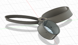
A new type of propeller I am using is the so-called “toroidal propeller.” If you can remember early schooling, you may recognize the word “torus” and the famous example of such a shape, a doughnut. Toroidal propellers are unique for using such a shape, having two “wings” per blade connected at the end. To make this propeller, I placed two oval shapes offset from the center, one on top and one on bottom. Connecting them with a “loft,” or edge-filling volume that I hollowed out, I created the rounded propeller shape in 2-, 3-, and 4-bladed variants.
For toroidal propellers and my two other variants (push and pull), I have printed sets of four, as would be found on a quadcopter. This will allow me to test multiple props of each design to minimize the effects of outliers, and in the case of unplanned propeller disassembly, I will have propellers to spare.
I finally pulled out the thrust tester that Pilot Institute uses for whole drones, which has a hook designed to latch onto a drone undercarriage. For my use case, this will be useless for testing a single propeller, as it would require impeccable balance and will be unstable. To solve this, I designed a new set of parts that can hold onto the hook and the prop motor simultaneously.
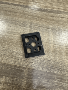
First, I designed a part that can screw onto the motor to test clearances. Note the large hole in the middle, needed to avoid the structures that hold the motor together. Drone motors use one of two mounting designs, either a 16mm-19mm or a 16mm-16mm mount. I designed for a 16mm gap between screws as that will be compatible with either design.
|
|
|

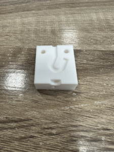
Next, I decided to design the hook-holding mechanism. The hooks are not standardized, so I had to figure out the shape myself. Also, because the piece has to hold the hook tight to stay rigid, I decided to design the piece much like a mold with a thick block indented with the hook’s shape. This left me with a few design considerations:
- The design would need two pieces in order to hold the hook on both sides.
- Each piece would therefore need to hold the motor and the other piece.
- The motor and hook will be on opposite sides, so the screws holding the motor will need to have a screwdriver-friendly path throughout the entire assembly.
- The hook will need to emerge from the assembly for connection to the thrust meter, so the hook silhouette will be flush with the part body.
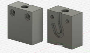
I designed the hook silhouette with a rectangle meeting the end of the body (Point 4) and a slot shape. An online protractor, used by holding the hook up to my screen, gave me a slot angle of around 115 degrees, though I eventually shifted that for better fit. I added two holes laterally through the body to hold each section together and recessed the exits so I could hide the nuts and bolts inside the rectangular shape – and so the nuts would be stuck in a certain angle and not loosen (Point 2). I kept the location of the motor-mount holes consistent, but added a larger hole throughout the body for screwing (Points 2 and 3). Then, I made a mirrored piece, separated it, and considered the design finished.

Attaching the pieces after printing, I found that the pieces fit together well, held up well to pulling and twisting, and mounted tightly to the motor and the hook. Overall, I am satisfied with my design and think it will work fine for testing single propellers, especially at the small scale I am using for my drone.


Next week, PI is moving to a new location, which is where most of my parts and tools have been hiding. Once PI has moved in, I will have access to the bolts and motors I need (Notice the empty holes where the two halves of the linkage are supposed to connect?), and a larger space to rev fans without bothering a room of video editors. I will start and finish my first round of propeller tests and report my results about Pull vs Push the effects of blade count on the toroidal propellers.
Propeller spreadsheet (Unchanged this week): https://docs.google.com/spreadsheets/d/1QnVORPgaP6eOXAQWGW8OxpOkJtlu77fsbD5rLiyG7hs/edit?usp=sharing.
Comments:
All viewpoints are welcome but profane, threatening, disrespectful, or harassing comments will not be tolerated and are subject to moderation up to, and including, full deletion.